085 CS
Vishay BCcomponents
Aluminum Capacitors
SMD (Chip) Standard
FEATURES
• Polarized aluminum electrolytic
non-solid electrolyte, self healing
capacitors,
S
• SMD-version, rectangular case, insulated
• Miniaturized, high CV per unit volume, low height
• Charge and discharge proof
N
• Flexible terminals, reflow and wave solderable
IG
• Supplied in blister tape on reel
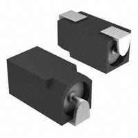
Fig.1 Component outlines
APPLICATIONS
longer
life
• General applications, consumer electronics, low profile
and lightweight equipment
E
139 CLL
• Decoupling, smoothing, filtering and buffering
D
085 CS
S
• SMD technology, boards with restricted mounting height
MARKING
The capacitors are marked (where possible) with the
following information:
QUICK REFERENCE DATA
8.8 x 3.7 x 3.9 and
11.9 x 3.7 x 3.9
E
Nominal case sizes
(L x W x H in mm)
Rated capacitance range, CR
Tolerance on CR
0.47 to 22 µF
N
- 10 to + 50 % or ± 20 %
Rated voltage range, UR
6.3 to 63 V
Category temperature range
- 40 to + 85 °C
Endurance test at 85 °C
Resistance to soldering
heat test
T
• Name of manufacturer
• ‘-’ sign indicating the cathode. The anode is identified by
bevelled edges
1500 hours
H22 represents 0.22 µF; 63 V
40 000 hours
2G2 represents 2.2 µF; 40 V
22C represents 22 µF; 6.3 V
500 hours
immersion in solder:
10 s at 260 °Cor 20 s at 215 °C
IEC 60384-18/CECC 32300
Table 1
RATED VOLTAGE MARKING CODE
UR (V)
6.3
10
16
25
40
63
C
D
E
F
G
H
Code letter
40/085/56
O
Climatic category IEC 60068
• Rated voltage code (see Table 1), the UR code letter
indicates the position of the decimal point in the
capacitance value
Examples for CR; UR marking:
R
Shelf life at 0 V, 85 °C
Based on sectional
specification
1000 hours
FO
Useful life at 85 °C
Useful life at 40 °C;
1.4 x lR applied
• Rated capacitance (in µF)
VALUE
W
DESCRIPTION
N
SELECTION CHART FOR CR, UR AND RELEVANT NOMINAL CASE SIZES (L x W x H in mm)
CR
(µF)
0.47
1.0
2.2
3.3
4.7
6.8
10
15
22
UR (V)
6.3
8.8 x 3.7 x 3.9
11.9 x 3.7 x 3.9
Document Number: 28300
Revision: 28-May-08
10
8.8 x 3.7 x 3.9
11.9 x 3.7 x 3.9
-
16
8.8 x 3.7 x 3.9
11.9 x 3.7 x 3.9
-
25
8.8 x 3.7 x 3.9
11.9 x 3.7 x 3.9
-
40
8.8 x 3.7 x 3.9
11.9 x 3.7 x 3.9
-
For technical questions, contact: aluminumcaps1@vishay.com
63
8.8 x 3.7 x 3.9
8.8 x 3.7 x 3.9
11.9 x 3.7 x 3.9
11.9 x 3.7 x 3.9
-
www.vishay.com
1
�085 CS
Aluminum Capacitors
SMD (Chip) Standard
Vishay BCcomponents
DIMENSIONS in millimeters
3.9
2 max. max.
2.7
max.
3.9
max.
4.1
max.
2.7
max.
N
2.7
max.
4.1
max.
3.9
max.
IG
2.7
max.
3.9
2 max. max.
2 max.
S
2 max.
10.8
12.2 max.
b.
S
7.5
9 max.
a.
b. Case size 11.9 x 3.7 x 3.9 mm
E
a. Case size 8.8 x 3.7 x 3.9 mm
D
Fig.2 Dimensional outlines
PACKAGING
MOUNTING
Tape on reel packaging: 2000 per reel
The capacitors are designed for automatic placement on
printed-circuit boards or hybrid circuits.
Optimum dimensions of soldering pads depend upon
soldering method, mounting accuracy, print lay-out and/or
adjacent components.
For recommended pad dimensions, refer to Fig. 3
and Table 2.
N
E
W
Detailed tape dimensions see section ‘PACKAGING’
Table 2
R
RECOMMENDED SOLDERING PAD DIMENSIONS in millimeters (placement accuracy ± 0.25 mm)
FOR REFLOW SOLDERING
NOMINAL CASE SIZE
LxWxH
FOR WAVE SOLDERING
C
D
E
F
G
8.8 x 3.7 x 3.9
9.7
3.5
2.9
2.5
3.0
10.1
4.4
13.5
4.1
4.7
3.7
2.9
14.0
8.4
11.9 x 3.7 x 3.9
12.9
6.5
2.9
2.5
6.0
13.3
4.4
16.8
7.4
4.7
3.7
6.1
17.3
8.4
FO
A
B
C
D
E
F
G
A
B
T
E
E
D G
G
N
O
D
C
B
B
C
A
A
F
F
reflow soldering
solder land/
solder paste
pattern
wave soldering
solder resist
pattern
occupied
area
tracks or
dummy tracks
Fig.3 Recommended pad dimensions for reflow and wave soldering
www.vishay.com
2
For technical questions, contact: aluminumcaps1@vishay.com
Document Number: 28300
Revision: 28-May-08
�085 CS
Aluminum Capacitors
SMD (Chip) Standard
Vishay BCcomponents
a
c
S
flow-direction of solder
d
IG
N
b
For dimensions a, b, c and d, refer to Table 3
Flow direction of solder preferably onto side-walls or plus-side of the capacitors
Fig.4 Minimum ditances between 085 CS capacitors on a printed-circuit board for wave soldering
For maximum conditions of different soldering methods see
Figs 5, 6 and 7.
E
AS A GENERAL PRINCIPLE, TEMPERATURE AND
DURATION SHALL BE THE MINIMUM NECESSARY
REQUIRED
TO
ENSURE
GOOD
SOLDERING
CONNECTIONS.
W
Table 3
Any temperature/time curve which does not exceed the
specified maximum curves may be applied.
D
Soldering conditions are defined by the curve, temperature
versus time. The temperature is that measured on the
soldering pad during processing.
S
SOLDERING
MINIMUM DISTANCES BETWEEN CAPACITORS in millimeters
Table4
amin.
bmin.
cmin.
dmin.
12
15
12
15
6.8
6.8
6.8
6.8
E
CASE
CODE
1a
1
N
NOMINAL CASE SIZE
LxWxH
8.8 x 3.7 x 3.9
11.9 x 3.7 x 3.9
CURING CONDITIONS FOR SMD-GLUE
MAX. Tamb
(°C)
125
140
150
160
FO
R
MAX. EXPOSURE TIME
(minutes)
10
3
1
0.5
280
TPad
260
(°C)
T
280
TPad
(°C) 260
240
220
220
200
200
180
180
160
160
140
140
120
120
100
100
N
O
240
80
80
0
50
100
150
200
f(s)
250
0
50
100
150
200
f(s)
250
Fig.5 Maximum temperature load during infrared reflow soldering Fig.6 Maximum temperature load during vapor phase reflow soldering
Document Number: 28300
Revision: 28-May-08
For technical questions, contact: aluminumcaps1@vishay.com
www.vishay.com
3
�085 CS
Aluminum Capacitors
SMD (Chip) Standard
Vishay BCcomponents
280
TPad
(°C) 260
240
220
S
200
180
N
160
140
IG
120
100
80
50
100
150
200
250
f(s)
S
0
E
Fig.7 Maximum temperature load during (double-) wave soldering
ELECTRICAL DATA
ORDERING EXAMPLE
D
DESCRIPTION
Electrolytic capacitor 085 series
CR
rated capacitance at 100 Hz
(tolerance - 10 to + 50 % or ± 20 %)
IR
rated RMS ripple current at 100 Hz, 85 °C
IL5
max. leakage current after 5 minutes at UR
Tan δ
max. dissipation factor at 100 Hz
Z
max. impedance at 10 kHz
10 µF/16 V; - 10/+ 50 %
Nominal case size: 11.9 x 3.7 x 3.9 mm; Form BR
W
SYMBOL
N
E
Ordering Code: MAL208525109E3
Former 12NC: 2222 085 25109
Note
R
Unless otherwise specified, all electrical values in Table 6 apply at
Tamb = 20 °C, P = 86 to 106 kPa, RH = 45 to 75 %.
Table 6
CR
100 Hz
(µF)
UR
(V)
10.0
T
6.3
N
16
25
40
63
www.vishay.com
4
ORDERING CODE MAL2085.......
NOMINAL
CASE SIZE
LxWxH
(mm)
IR
100 Hz
85 °C
(mA)
IL5
5 min
(µA)
Tan δ
100 Hz
Z
10 kHz
(Ω)
8.8 x 3.7 x 3.9
11
3.1
0.30
- 10/+ 50 %
± 20 %
BLISTER TAPE
ON REEL FORM BR
BLISTER TAPE
ON REEL FORM BR
20
23109E3
63109E3
63229E3
22
11.9 x 3.7 x 3.9
20
3.3
0.30
9
23229E3
6.8
8.8 x 3.7 x 3.9
10
3.1
0.25
24
24688E3
64688E3
15
11.9 x 3.7 x 3.9
18
3.3
0.25
11
24159E3
64159E3
O
10
FO
ELECTRICAL DATA AND ORDERING INFORMATION
4.7
8.8 x 3.7 x 3.9
9
3.2
0.20
26
25478E3
65478E3
10
11.9 x 3.7 x 3.9
16
3.3
0.20
12
25109E3
65109E3
3.3
8.8 x 3.7 x 3.9
8
3.2
0.18
27
26338E3
66338E3
6.8
11.9 x 3.7 x 3.9
14
3.3
0.18
13
26688E3
66688E3
2.2
8.8 x 3.7 x 3.9
7
3.2
0.16
32
27228E3
67228E3
4.7
11.9 x 3.7 x 3.9
13
3.4
0.16
15
27478E3
67478E3
0.47
8.8 x 3.7 x 3.9
4
3.1
0.10
120
28477E3
68477E3
1.0
8.8 x 3.7 x 3.9
6
3.1
0.12
55
28108E3
68108E3
2.2
11.9 x 3.7 x 3.9
11
3.3
0.14
25
28228E3
68228E3
3.3
11.9 x 3.7 x 3.9
13
3.4
0.14
17
28338E3
68338E3
For technical questions, contact: aluminumcaps1@vishay.com
Document Number: 28300
Revision: 28-May-08
�085 CS
Aluminum Capacitors
SMD (Chip) Standard
Vishay BCcomponents
Table 7
ADDITIONAL ELECTRICAL DATA
PARAMETER
CONDITIONS
VALUE
Voltage
Us ≤ 1.15 x UR
Reverse voltage
Urev ≤ 1 V
after 1 minute at UR
IL1 ≤ 0.02 CR x UR + 3 µA
after 5 minutes at UR
IL5 ≤ 0.002 CR x UR + 3 µA
nominal case size 8.8 x 3.7 x 3.9 mm
typ. 11 nH
nominal case size 11.9 x 3.7 x 3.9 mm
typ. 13 nH
IG
Leakage current
N
Current
Resistance
calculated from tan δmax and CR (see Table
D
1.2
C
C0
E
1
2
3
W
CAPACITANCE
1.1
N
3
R
2
0.9
- 40
- 20
FO
1
0.8
ESR = tan δ/2 πf CR
E
Equivalent series resistance (ESR)
1.0
S
Inductance
Equivalent series inductance (ESL)
S
Surge voltage for short periods
0
C0 = capacitance at 20 °C, 100 Hz
20
40
1
2
3
0.9
3
0.8
2
0.7
Curve 1: 6.3 V
Curve 2: 25 V
Curve 3: 63 V
60
80
Curve 1: 6.3 V
Curve 2: 25 V
Curve 3: 63 V
0.6
100
Tamb (20 °C)
Fig.7 Typical multiplier of capacitance as a function of
ambient temperature
10
1
102
C0 = capacitance at 20 °C, 100 Hz
103
104
Tamb (20 °C)
Fig.9 Typical multiplier of capacitance as a function of frequency
N
O
T
1.1
C
C0
1.0
Document Number: 28300
Revision: 28-May-08
For technical questions, contact: aluminumcaps1@vishay.com
www.vishay.com
5
�085 CS
Aluminum Capacitors
SMD (Chip) Standard
Vishay BCcomponents
RIPPLE CURRENT AND USEFUL LIFE
CCC205
IA
3.2
IR
3.1
S
3.3
N
3.0
2.8
IG
2.6
2.4
0
2.
E
5
1.
2.0
0
3.
1.8
0
4.
6
D
1.6
.0
10
1.4
15
20
W
50
70
IA = actual ripple current at 100 Hz.
IR = rated ripple current at 100 Hz, 85 °C
(1) Useful life at 85 °C and IR applied: 1500 hours
(1)
30
1.2
1.0
0.8
0.5
0.0
lifetime multiplier
0
1.
S
2.2
50
60
70
80
90
E
40
100
Tamb (°C)
N
Fig.10 Multiplier of useful life as a function of ambient temperature and ripple current load
R
Table 8
FREQUENCY
(Hz)
50
100
IR MULTIPLIER
UR = 6.3 to 16 V
UR = 25 to 40 V
UR = 63 V
0.80
0.75
0.70
1.00
1.00
1.00
1.20
1.30
1.55
1000
1.35
1.55
1.90
3000
1.45
1.70
2.30
1.50
1.80
2.50
O
T
300
FO
MULTIPLIER OF RIPPLE CURRENT (IR) AS A FUNCTION OF FREQUENCY
N
≥ 10 000
www.vishay.com
6
For technical questions, contact: aluminumcaps1@vishay.com
Document Number: 28300
Revision: 28-May-08
�085 CS
Aluminum Capacitors
SMD (Chip) Standard
Vishay BCcomponents
TEST PROCEDURES AND REQUIREMENTS
TEST
NAME OF TEST
PROCEDURE
(quick reference)
REFERENCE
REQUIREMENTS
IEC 60384-18,
subclause 4.3
shall be performed prior to tests
mentioned below;
method: reflow or (double-) wave
soldering;
for maximum temperature load
refer to chapter “Mounting”
ΔC/C: ± 10 %
tan δ ≤ spec. limit
IL5 ≤ 2 x spec. limit
Endurance
IEC 60384-18/
CECC 32300,
subclause 4.15
Tamb = 85 °C; UR applied;
1000 hours
ΔC/C: ± 20 %
tan δ ≤ 2 x spec. limit
Z ≤ 3 x spec. limit
IL5 ≤ spec. limit
Useful life
CECC 30301, subclause 1.8.1
Tamb = 85 °C; UR and IR applied;
1500 hours
Shelf life
(storage at high temperature)
IEC 60384-18/
CECC 32300,
subclause 4.17
Tamb = 85 °C; no voltage
applied;
500 hours
D
E
S
IG
N
S
Mounting
ΔC/C, tan δ, Z:
for requirements
see ‘Endurance test’ above
IL5 ≤ 2 x spec. limit
N
O
T
FO
R
N
E
W
after test: UR to be applied for
30 minutes, 24 to 48 hours
before measurement
ΔC/C: ± 50 %
tan δ ≤ 3 x spec. limit
Z ≤ 3 x spec. limit
IL5 ≤ spec. limit
no short or open circuit
total failure percentage: ≤ 3 %
Document Number: 28300
Revision: 28-May-08
For technical questions, contact: aluminumcaps1@vishay.com
www.vishay.com
7
�Legal Disclaimer Notice
Vishay
Disclaimer
All product specifications and data are subject to change without notice.
Vishay Intertechnology, Inc., its affiliates, agents, and employees, and all persons acting on its or their behalf
(collectively, “Vishay”), disclaim any and all liability for any errors, inaccuracies or incompleteness contained herein
or in any other disclosure relating to any product.
Vishay disclaims any and all liability arising out of the use or application of any product described herein or of any
information provided herein to the maximum extent permitted by law. The product specifications do not expand or
otherwise modify Vishay’s terms and conditions of purchase, including but not limited to the warranty expressed
therein, which apply to these products.
No license, express or implied, by estoppel or otherwise, to any intellectual property rights is granted by this
document or by any conduct of Vishay.
The products shown herein are not designed for use in medical, life-saving, or life-sustaining applications unless
otherwise expressly indicated. Customers using or selling Vishay products not expressly indicated for use in such
applications do so entirely at their own risk and agree to fully indemnify Vishay for any damages arising or resulting
from such use or sale. Please contact authorized Vishay personnel to obtain written terms and conditions regarding
products designed for such applications.
Product names and markings noted herein may be trademarks of their respective owners.
Document Number: 91000
Revision: 18-Jul-08
www.vishay.com
1
�


 工商网监
湘ICP备2023018690号
工商网监
湘ICP备2023018690号
